Monthly Archives: October 2009

Do you really display PNGs?

Digging up the luma palette images reminded me of a useful PNG I made back around 1996 or so, back when this file format was quite new. A peculiarity of the PNG file format is that it stores alpha separately, unmultiplied. For 3D work it is the norm for the color stored to be premultiplied by the alpha. I won’t go into the how and why; this topic is covered in our book on pages 139-140 and is discussed on Wikipedia, among many other places.

One nice feature of premultiplied images is that you can just ignore the alpha channel entirely when displaying them for preview. This is equivalent to compositing the image over a black background. With PNG, you are required to examine the alpha channel and multiply the RGB by it in order to get the right color to display. Unmultiplied alpha has a 2D photo sense to it, the RGB image exists everywhere and the alpha is masking some part of it. The alpha is not an integral part of the pixel, as it is in 3D.

On to the image:

alpha_test

I cobbled this together to be able to quickly check if a particular piece of software was respecting the alpha channel in PNG. Back then, most software didn’t, so what would be displayed is “This viewer does not support transparency”. Today, it’s pretty rare to find such flawed PNG readers commercially (I couldn’t find a current example for you to try). Still, I’ve found this image useful as a quick reality check for whether software is using the alpha in a PNG.

Lest we forget, it was the LZW patent in the GIF format that helped popularize PNG as a patent-free alternative for the web. The Unisys patent finally fully expired back in July 2004, so it’s a moot point now, but for awhile this was a patent enforced for tens of millions of dollars, with over 2,000 licensees. My favorite quote on the whole controversy was from a flak at Unisys giving spin about their positive role enforcing a patent on a technology unknowingly used in a file format that they didn’t invent:

But Unisys credited its exertion of the LZW patent with the creation of the PNG format, and whatever improvements the newer technology brought to bear.

“We haven’t evaluated the new recommendation for PNG, and it remains to be seen whether the new version will have an effect on the use of GIF images,” said Unisys representative Kristine Grow. “If so, the patent situation will have achieved its purpose, which is to advance technological innovation. So we applaud that.”

NVIDIA Jumps on the Cloud Rendering Bandwagon

In January, AMD and OToy announced Fusion Render Cloud, a centralized rendering server system which would perform rendering tasks for film and even games, compressing the resulting video and sending it over the internet.  In March, OnLive announced a similar system, but for the entire game, not just rendering.  Now NVIDIA has announced another cloud rendering system, called RealityServer, running on racks of Tesla GPUs (presumably using Fermi in future iterations).  This utilizes the iray ray tracing system developed by mental images, who also make mental ray (mental images has been owned by NVIDIA since 2007).

The compression is going to be key, since it has to be incredibly fast, extremely low bit rate and very high quality for this to work well.  I’m a bit skeptical of cloud rendering at the moment but maybe all these companies (and investors) know something I don’t…

Constant Luma Palette

I was looking around my image files and found this:
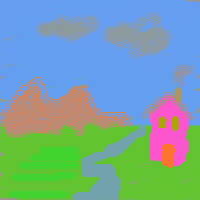
Constant luminance image

I made this incredibly hideous drawing back in 2001. What’s interesting about it is that if you convert this image to grayscale, using say Irfanview or XnView, it disappears entirely into a solid gray. Download and try converting it with your favorite image manipulation program (I refuse to insert a solid gray image of it here as “proof”).

Here’s the palette I used, in image form; the perl program for creating it is at the end of this post.

LUMA_PAL

My goal was to make a palette where you could draw anything, knowing that if it were converted to grayscale (e.g., via a scanner, or printed on a monochrome printer) it would become illegible. A similar technique was used long ago as a copy protection scheme for documentation for some computer games: print black on dark red and a photocopier would typically return all-black. Perhaps publishers that are against Google Books’ scanning of their works will use such a palette someday… I can only hope not.

What I found interesting about this little experiment was how differently we perceive the various colors compared to the constant luma computed. Grayscale conversion is supposed to take colors with the same impact and give them the same gray level. In my drawing, that pink is way brighter than the gray clouds, and even the green streaks on the ground at the lower left are brighter than the rest of the ground plane. It makes me wonder if there’s some better conversion to grayscale that more closely matches our perception of impact. Wikipedia mentions luminance as just one strategy; are there others that work better (on average)? Info, anyone? Update: a keynote at I3D 2022 by Dr. Margaret S. Livingstone discussed this very effect in depth; see her book Vision and Art for information about it.

Luma

So what’s luma, versus luminance? It turns out that the formula we typically use to convert to grayscale is flawed, in that what should happen is that the color to be converted should be put in a linear space, converted to grayscale, then gamma corrected. By applying the grayscale formula (see below) to the displayed image data directly, what most every image manipulation program typically does, we get the order wrong. However, it’s a lot more work to “uncorrect” the gamma (make the image’s channels represent linear values), apply a grayscale formula, and then gamma correct. Long and short, the grayscale value computed without taking into account gamma is called “luma”, to differentiate it from a true luminance value.

You can find more about this in Poynton’s color FAQ and Wikipedia, and details about the difference this makes can be found here. Relevant quote from this last source: “…introduces a few image artifacts that are usually fairly minor. The departure from the theoretically correct order of operations is apparent in the dark band seen between the green and magenta color bars of the standard video test pattern.”

I decided to reformulate the palette today and see what it looks like with constant luminance instead of luma, by raising the normalized palette values to the power 0.45. There’s a definite difference, as expected:


lumapal10x luminancepal10x luminancepal8

Left is the original luma palette, zoomed up (hmmm, should have used nearest neighbor); middle is the luminance palette, with gamma correction; right is another “slice” of the luminance palette, having 0.8 being the highest linear green value. These right two images do look more equivalent in visual impact to me. So a better perceptual grayscale, I suspect, is to correctly account for gamma. Trying this rightmost palette out, the image becomes:
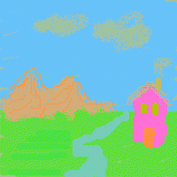
LUMINANCE_IMG

This looks a lot better to me, more equal. The green streaks on the ground are hardly noticeable now, for example. The pink house still looks a bit bolder than the rest, but otherwise is pretty reasonable. I’ll bet if I used the newer grayscale formula (see below) the pink might fade further—well, enough hacking for the day or I’ll never get this post done.

LCD brand does matter: my Dell LCD displays the image fine from most angles, the Macbook Pro screen definitely varies with vertical angle in particular, and it’s hard to know what the “right” angle is. Using Steve Westin’s old gamma page and aiming for 2.2 seemed to work.

In case you’re curious, here’s what the grayscale image looks like for this luminance-balanced image, using XnView:
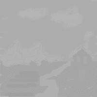
LUMINANCE_grayscale

Which to me emphasizes the weaknesses of using luma instead of luminance: the house is darker, the clouds are lighter in grayscale? Not to my eye.

Gory Details

Conversion to luma Y’ grayscale uses a formula such as:

Y’ = 0.212671*R’+ 0.715160*G’+ 0.072169*B’

from Poynton’s color space FAQ; it’s the common form for contemporary CRTs.

Or older ones such as:

0 299
0 587
0 114
’ = ’
+ ’
+ ’

Y’ = 0.299*R’ + 0.587*G’ + 0.114*B’

from Poynton’s FAQ and used in his Digital Video and HDTV: Algorithms and Interfaces. This is the one I used back in 2001.

Or:

Y’ = 0.2904*R’ + 0.6051*G’ + 0.1045*B’

from Dutré’s useful Global Illumination Compendium – download it free.

Here’s the Perl program, which outputs to a PPM file.

printf "P3\n16 16\n255\n";
for ( $r = 0 ; $r < 16 ; $r++ ) {
    for ( $b = 0 ; $b < 16 ; $b++ ) {
        $red = $r * 255 / 15 ;
        $blue = $b * 255 / 15 ;
        # The 255 below can be set in the range 180-255 for different constant palettes.
        $green = 255 - $red*0.299/0.587 - $blue * 0.114/0.587 ;
        printf( "%d %d %d%s", $red+0.5, $green+0.5, $blue+0.5, ($b==15)?"":" " ) ;
    }
    printf("\n") ;
}

If you make the starting point for green lower than 180, the green channel would take on negative values.

printf "P3\n16 16\n255\n";
$gamma = 1/0.45;
for ( $r = 0 ; $r < 16 ; $r++ ) {
    for ( $b = 0 ; $b < 16 ; $b++ ) {
        $red = $r/15;
        $blue = $b/15;
        # The 0.8 below can be set in the range 0.703 to 1 for different constant palettes.
        $green = 0.8 - $red*0.299/0.587 - $blue * 0.114/0.587 ;
        # gamma correct
        $red = 255 * $red**(1/$gamma);
        $green = 255 * $green**(1/$gamma);
        $blue = 255 * $blue**(1/$gamma);
        printf( "%d %d %d%s", $red+0.5, $green+0.5, $blue+0.5, ($b==15)?"":" " ) ;
    }
    printf("\n") ;
}

Award-Winning Architectural Renderings

I don’t know much about architectural renderings; I guess I always thought of them as utilitarian.  This page of award-winners proved me very wrong – there is true artistry on display here.  The bottom of the page also has a real-time category; of the five nominees in that category three (including the winner – Shockwave required) are available to view online.

SMOG Results

My wife just told me about the SMOG readability formula, which is evidently widely used. “SMOG” stands for Simple Measure of Gobbledygook. It looks for the number of polysyllabic words (3 syllables or more) used in a document. The square root of the result of dividing the number of polysyllabic words by the number of sentences is used to derive a readability grade level; read more on Wikipedia.

I ran the calculator here on a few passages in our book (those without equations, which I thought would throw the calculator off): Deferred Shading, Fresnel Equation, Scene Graphs, and the final chapter. Scene Graphs was simplest, at 12.56, Fresnel hardest, at 14.1. On average the level was a bit above 13, meaning College Freshman level. Pieces such as this one weigh in at 17.12. I took a piece of text from Hearn and Baker’s old Computer Graphics, C Version, 2nd Edition, on Fractals, and it came up as 14.47. So our book’s no Hop on Pop, but it’s at least not horrifically hard and seems in the ball park for our target audience.

By the way, this post’s SMOG grade is 11.21.

SIGGRAPH 2009 Course Pages

The organizers of SIGGRAPH Courses often put up web pages dedicated to the course.  These typically have the latest version of the course notes and the slides.  I’ve found a bunch of SIGGRAPH 2009 course pages, and thought it would be convenient to have them all in one place:

SIGGRAPH courses are a consistently good source of information – if any of these courses are about a topic which interests you, you might want to take the time to read the course notes and slides.

Looping Through Polygon Edges

We mostly avoid coding issues in our book, as our focus is on algorithms, not syntax and compiler vagaries. There’s a coding trick that I want to pass on, as it’s handy. Graphics programmers appear to be divided into two groups with this method: those who think it’s intuitively obvious and learnt it on their pappy’s knee, and those who never saw it before and are glad to find out.

You want to loop through the edges of a polygon. The vertex data is stored in some array vertexData[count], an array of count of some sort of Vertex data structure. The headache is attaching the last and first vertices together to make the connecting edge. There are plenty of weak ways to walk through the edges and connect last and first:

  • Double the beginning vertex so it’s added to the end of array; the final edge is then just another pair of adjacent points. This is perhaps even fastest to actually execute but is generally a hideous solution, adding a copy of a vertex to the array.
  • Form the last edge explicitly, outside the loop. Poor for maintenance, as you then need to copy whatever other code is inside the loop to be called one more time.
  • Use an “if” statement to know if you’re at the end of the loop; if so, then connect the first and last vertices for the last edge. The “if” special case is needed for only one vertex, which is wasteful and we’d like to avoid “ifs”.
  • Use modulo arithmetic on the counter for one of the vertices, so that it loops back to the start.

Modulo isn’t terrible, but is overkill and costs processing speed, as the modulo operation is truly needed for only the very last iteration:

for ( int v = 0; v < count; v++ ) {
   // access vertexData[v] and vertexData[(v+1)%count] for the edge
}

Here’s the solution I prefer:

for ( int v1 = count-1, int v2 = 0; v2 < count; v1 = v2++ ) {
   // access vertexData[v1] and vertexData[v2] for the edge
}

The simple trick is that v1 starts at the end of polygon, so dealing with the tough “bridge” case immediately; v2 counts through the vertices, and v1 follows behind. You can, similarly, make a pointer-based version, updating the pV1 pointer by copying from pV2. If register space is at a premium, then modulo might be a better fit, but otherwise this loop strikes me as the cleanest solution.

This copy approach can be extended to access any number of neighboring vertices per iteration. For example, if you wanted the two vertices vp and vn, previous and next to a given vertex, it’s simply:

int vp, v, vn;
for ( vp = count-2, v = count-1, vn = 0; vn < count; vp = v, v = vn++ ) {
   // access vertexData[vp], [v], [vn] for the middle vertex v.
}

I’ve seen this type of trick in code in Geometric Tools, and Barrett formally presents it in jgt. I mention it here because I think it’s a technique every computer graphics person should know.