Author Archives: Eric

Seven Things for April 2, 2015

I haven’t made one of these link posts for awhile. This one’s recent news, the ones to come will have more fun stuff.

sadly, human computers mostly got “calculate this boring number” assignments and very rarely got “if i was james counterstrike and i fired this rpg at this nightorc tell me how many gibs would come out”: one of history’s true missed opportunities

WebGL Links Page

I got tired of re-finding various useful WebGL and three.js links, so I made a page:

http://www.realtimerendering.com/webgl.html

What cool things am I missing?

I’ve made it a page of links I am likely to want to check out in the future. It’s a bit hard to draw the line. For example, I didn’t bother adding fun demos such as this and this, but I did add the page where I browse new demos. I don’t list development systems such as Goo Create for non-programmers, which is built on this open-source WebGL engine and has some interesting features. Nice things all, but I personally am unlikely to come back to them (or if I do, they’re now in this blog post).

One more variable…

Michael Cohen was looking at John Hable’s useful test image:

He noticed an odd thing. Looking at the image on his monitor (“an oldish Dell”) from across the room, it looked fine, the 187 area matched the side areas:

ok

(yes, ignore the moires and all the rest – honestly, the 187 matches the side bars.)

However, sitting at his computer, the 128 square then matched the side bars:

bad

Pretty surprising! We finally figured it out, that it’s the view angle: going off-axis resulted in a considerably different gray appearance. Moving your head left and right didn’t have much effect on the grays, but up and down had a dramatic effect.

Even knowing this, I can’t say I fully understand it. I get the idea that off-axis viewing can affect the brightness, but I would have thought this change would be consistent: grays would be dimmed down the same factor as whites. That last image shows this isn’t the case: the grays may indeed be dimmed down, but the alternating white lines are clearly getting dimmed down more than twice as much, such that they then match the 128 gray level. It’s like there’s a different gamma level when moving off-axis. Anyone know the answer?

Addendum: and if you view the first image on the iPhone, you get this sort of thing, depending on your zoom level. Here’s a typical screen shot – I’ve trimmed off the right so that the blog will show one pixel for pixel (on desktop computers – for mobile devices you’re on your own). This darkening is from bad filtering, see the end of this article.

iphone

Follow-up: one person commented that it’s probably a TN panel. Indeed, there’s a video showing the tremendous shift that occurs. The blue turning to brown is particularly impressive. I haven’t yet found a good explanation of what mechanism causes this shift to occur (Wikipedia notes other monitors having a gamma shift, so maybe it is something about gamma varying for some reason). There’s a nice color shift test here, along with other interesting tests.

Even better: check out this amazing video from Microsoft Research. (thanks to Marcel Lancelle for pointing it out)

Sci-Hub

Here’s a fascinating article on Sci-Hub, the “Pirate Bay” of scientific research papers. Really, go read it.
 
My sympathy lies with Alexandra Elbakyan. The key points to me are that researchers already informally download or ask other researchers for preprints. Sci-Hub wastes less time for this process. In physical terms, the very minor value-added of the final copy vs. the author’s draft is the main thing being “stolen”. Given that researchers make no royalties off the papers, there’s no loss to them there. The main thing journals sell is prestige.
 
That said, I don’t want journals to die on the vine, they deserve some money (though certain publishers seem way too profitable). I don’t see a good solution to these constraints:
  • Research papers should be free to anyone to access, especially since the authors do not earn royalties and want their papers to be read.
  • Publishers deserve to eat. Update: by which I mean, whoever is hosting and maintaining the journal deserves some reasonable amount of money. I don’t subscribe to the “people making buggy whips should have their jobs maintained and the automobile should be outlawed” school of thought.
In a sense, we already have a solution: author pre-prints are sometimes available on their websites. Google Scholar does a fairly good job finding these. But gathering these pre-prints on a single site is considered illegal; pre-prints themselves are probably illegal since the publisher usually owns the final article, but publishers rarely attack their unpaid writers the researchers to take their own work off their own sites. So the pre-print solution is not very good. It’s spotty coverage at best and the number of authors’ sites decrease over time as they move or die. A more permanent repository is needed.
One solution to the problem is the one-time fee to the journal to coordinate peer review (which is usually done by an unpaid editor researcher anyway) and publish the article (layout is done by the researcher, which is the norm in my field). If these fees were, say, $200 for a 12 page paper, great (well, not great, but at least understandable). For the publishers that allow this form of payment, it’s more like $2000 on up.
 
Another solution is to no longer use a paid publisher. Online journals such as the Journal of Computer Graphics Techniques are where there is no paid publisher involved, and a university provides permanent storage and distribution of the contents. In this model there are literally no costs to the researchers or readers, just the university or other institution pursuing its mission of the dissemination of information. There’s plenty of other things for publishers to publish and market and distribute, so they’ll still eat.
 
Back when journals and article reprints were on paper, and when layout and distribution was done by the publisher, $25/paper costs made sense. The internet and websites aren’t free, but nearly so. So why the high fees? Because they can.

A PNG Puzzle

Last post was too long, covering too much terrain. Here’s a puzzle instead which whittles it all down.

What values do you store in an sRGB PNG to display a perceptually half-gray color, with an alpha of 0.5?

If you’re an absolute expert on PNG and perception and alpha, that’s all the information you need. Just in case, to make sure you don’t break any rules, here are the key bits:

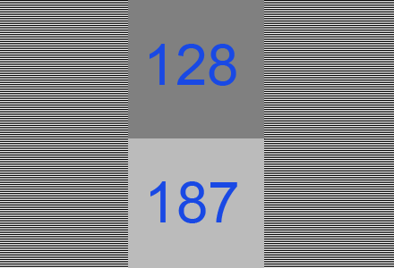
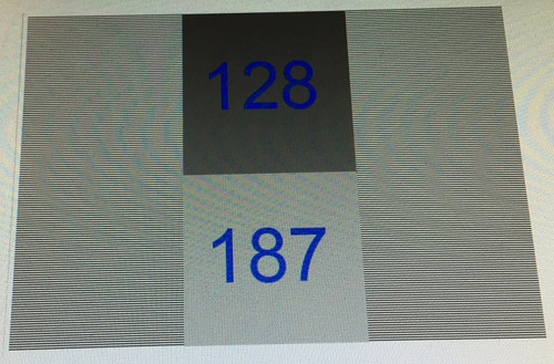
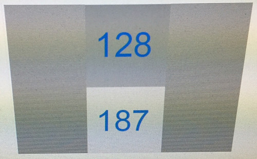
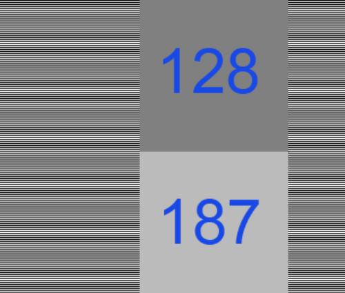
  1. A perceptually half-gray color on the screen is (187,187,187), not (128,128,128). See the image below to prove this to yourself, which is from John Hable’s lovely article.
  2. Your PNG is saving values in sRGB space. No extremely-rare gamma = 1.0 PNG for you.
  3. Alpha is coverage. The PNG spec notes, “The gamma value has no effect on alpha samples, which are always a linear fraction of full opacity.”
  4. PNG alphas are unassociated, they do not premultiply the color. To display your sRGB PNG color composited against black, you must multiply it by your unassociated alpha value.

So, what do you store in your PNG image to get a half-gray color displayed, with an alpha of 0.5? A few hints, then the answer, is after the image below.

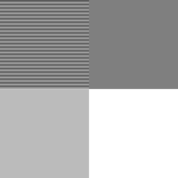
Horizontal fully-black and fully-white lines combine to a half-gray, represented by 187. That’s sRGB in action:

Hint #1: a half-gray color with an alpha of 1.0 (fully opaque) is stored in a PNG by (187,187,187,255).

Hint #2: if a PNG could store a premultiplied color, the answer would be (187,187,187,128).

Hint #3: to turn a premultiplied color into an unassociated color, divide the color by the (fractional) alpha.

And just to have something between you and the answer, here’s this, from I wish I knew where.

d424a80f76e16bf552a09fae02fee808_59445

The answer is (255,255,255,128), provided by Mike Chock (aka friedlinguini), who commented on my post – see the comments below. My answer was definitely wrong, so I’ll explain why this answer works.

The PNG spec notes, “This computation should be performed with intensity samples (not gamma-encoded samples)”. So, to display an sRGB-encoded PNG, you must do the following:

  1. Convert the sRGB color to linear space. For (255,255,255,128) this gives (1.0,1.0,1.0).
  2. Now multiply in the alpha, to get a linear premultiplied value. Times (128/255) -> 0.5 gives (0.5,0.5,0.5).
  3. Convert this value back to sRGB space and display it. This gives (187,187,187) as the color to display.

Me, I thought that PNGs with sRGB values and alphas were displayed by simply multiplying the sRGB by the stored alpha. Wrong! At least, by the spec. How could I think such a crazy thing? Because every viewer and every browser I tested showed this to be how such a PNG was displayed.

So, I’m very happy to find PNG is not broken; it’s simply that no one implements it correctly. If you do know some software that does display this image properly (your browser does not), let me know – it’ll be my example of how things should work.

Update: as usual, Jim Blinn predates my realizations by about 18 years. His article “A Ghost in a Snowstorm” (collected in the book Notation, Notation, Notation; most of this article can be found here) talks about the right way (linearization) and the errors caused by the various wrong ways of encoding alpha and sRGB. Thanks to Sean Barrett for pointing it out.

My conclusion remains the same: if you want fun puzzles and you’re near a big city, check out The Puzzled Pint, a great free social puzzle event each month.

For the record, here’s my original wrong answer:

The answer is (373,373,373,128). To display this RGBA correctly, you multiply by the alpha (and divide by 255, since the value 128 represents 0.5) to get (187,187,187).

And that’s the fatal flaw of sRGB PNGs in a nutshell: you can’t store 373 in 8 bits in a PNG. 16 bits doesn’t help: PNGs store their values as fractions in the range [0.0, 1.0].

No linearization or filtering or order of operations or any such thing involved, just a simple question. Unfortunately, PNG fails.

Wrong answers include:

  • (187,187,187,128) – this would work if PNG had a premultiplied mode. It does not, so this color would be multiplied by 0.5 and displayed as (94,94,94). That said, this is a fine way to store the data if you have a closed system and no one else will ever use your PNGs.
  • (187,187,187,255) – this will display correctly, but doesn’t keep the alpha around.
  • (255,255,255,128) – this gives you a display value of (128,128,128) for the color, which Hable’s image shows is not a perceptual half-gray. If you used the PNG gamma chunk and set gamma to 1.0, this would work. Almost no one uses this gamma setting (it causes banding unless you use 16 bits) and it’s rarely supported by most tools.
  • (255,255,255,187) – you break the PNG spec by sRGB correcting the alpha. This will actually display correctly, (187,187,187). If you composite this image over some other image with an alpha, this wrong alpha fails.
  • (255,255,255,187) again – you decide to “remember” the alpha is sRGB corrected and will uncorrect it before using it as an alpha elsewhere. If you want to break the spec, better to go with storing a premultiplied color, the first wrong answer. This fix is confusing.
  • (255,255,255,128) again – you store the correct alpha, but require that you first convert the stored color from sRGB to linear before applying the alpha, then convert the color back to sRGB to display it. This will work, but it defies radiance and alpha theory, it’s convoluted, expensive, super-confusing, not how anyone implements PNG display, and not how the spec reads, as I understand it. Better to just store a premultiplied color.

I wish my conclusion was wrong, but I don’t see any solution short of adding a new chunk to the PNG spec. My preference is adding a chunk that notes the values are stored as premultiplied.

In the meantime, if you want solvable puzzles and you’re near a big city, check out The Puzzled Pint, a great free social puzzle event each month.

Addendum

Zap Andersson debated this puzzle with me on Facebook, and many thanks to him. He prefers the solution (255,255,255,128), applying the alpha “later.” To clarify, here’s how PNGs are normally interpreted (and I think this follows the spec, though I’d be happy to be proven wrong, as then PNG would still work, even if no viewer or browser I know currently implements it correctly):

To display a PNG RGBA in sRGB: you multiply the RGB color by the alpha (expressed as a fraction).

The “later” solution to display a PNG RGBA in sRGB: you convert the sRGB number stored to a linear value, you then apply the alpha, and then you convert this linear value back to sRGB for display.

I like this, as convoluted as it is, in that it makes PNG work (I really don’t want to see PNG fail). The problem with this solution is that I don’t think anyone does it this way; browsers certainly don’t.

The other interesting thing Zap points out is this interesting page, which points to this even more relevant page. My takeaway is that I shouldn’t talk about 187-gray as the perceptually average gray; 128 gray really does look perceptually more acceptable (which is often why gamma correction is justified, that human perception is non-linear along with the monitor – I forgot). This doesn’t actually change anything above, the “half-covered pixel” example should still get a display level of 187. This is confirmed by alternating full-black and full-white lines averaging out to 187, for example.

PNG + sRGB + cutout/decal AA = problematic

[TL;DR? Go try the puzzle instead.]

A few questions came out of my blog entry on GPUs preferring premultiplication from various people, including myself. Let’s nail them down one by one, then add these bits up to explain why PNG is not very good at storing antialiased cutout and decal images (images which have an alpha component) that were generated using physically-based rendering. It turns out it’s not PNG’s fault, it’s the implementation used by PNG viewers. I provide two downloadable PNG images to test your own viewer or renderer to determine whether sRGB and compositing are working properly.

If you’re already convinced that you should do filtering (and most every other computation) in linear space, skip the first section. If you already know that you should think of linear values for a pixel as intrinsically premultiplied, since they represent radiance for the pixel, skip two sections. If you know that viewers and browsers don’t blend PNGs with alphas properly, skip to the conclusions at the very end and see if you agree. Me, I’m still learning, so can imagine I made a goof along the way (update: and indeed I did!), though I’ve tried very hard not to do so. I’m honestly surprised how many viewers and browsers (perhaps all?) don’t perform display, filtering, and compositing correctly for this image type.

Don’t Filter in sRGB

This should be one of those things everyone knows by now, but just in case…

So you have three texels and two colors you’ve stored in a PNG, red and green:

rg_interp

Interpolating between these two colors equally, what’s the color (that you store in the PNG) of the center texel? The answer is not (128, 128, 0), the average of the two texels on the ends. You can sort-of tell by just looking at the result:

rg_interp2

The right answer is:

rg_interp3

You shouldn’t interpolate or otherwise filter when in sRGB (essentially, gamma corrected) space, that’s why it looks bad. You shouldn’t do this because sRGB is non-linear – linear operations such as addition and multiplication don’t work properly. Update: see this link, for example – the bus license plate is a good example.

Instead you want to convert from sRGB to linear space, interpolate in linear space, and then convert back to sRGB (equations here). It’s also what you want to do to get good mipmaps, or anything else where you’re using multiple samples to get a new value. My favorite article on this is Larry Gritz’s from GPU Gems 3. There’s also a nice recent article about this workflow on the Renderman Community site, showing how to convert textures to linear space, do lighting there, then convert back for display. If these articles don’t convince you that linearization is necessary, I’m not sure what would.

Here’s another example, sRGB interpolation vs. the correct linear interpolation over a band of about 4 texels in width:

rgb_bad   rgb_good

The sRGB interpolation gives a black band, the correct linear interpolation gives a smooth transition (personally I see a more yellowish transition, which makes sense since it’s over a few pixels, but the general brightness is the thing to notice the most here; if you back up a bit the yellow goes away but the black band in the first image is still there. On a phone you may have to zoom in).

Premultiply before converting to sRGB

Say you’re computing the coverage of a triangle you’re rendering, in linear space. It covers half the area of some pixel, alpha = 0.5. You compute the color of the triangle covering half this pixel, and the color is (1.0, 0.0, 0.0). I’m going to use floating point triplets here for colors in linear space; sRGB maps these values to displayable values we store in, say, a PNG image file.

Normally you take your color, clamp or otherwise map each of the RGB values to [0.0, 1.0] (possibly using tone mapping), and then convert to sRGB for display and storage. The question is: do you first premultiply your color by alpha, then convert to sRGB, or vice versa?

It’s clear you don’t modify the alpha coverage itself by sRGB. Coverage is coverage, it remains the same in any color space. What coverage represents is how much of a surface is visible in a pixel. If you think about it, our half-covered pixel with a (1.0, 0.0, 0.0) surface color on the triangle should emit the same amount of radiance as a fully-covered pixel that has a surface color of (0.5, 0.0, 0.0). The only way to get these to be equivalent is to multiply by the alpha first, then convert the resulting color to sRGB. As Larry Gritz succinctly put it, “radiance is associated,” that is, the area of the emitter in the pixel matters. The radiance is computed by including the area coverage term in the computations.

So, the order is linear space -> premultiply the result to get the radiance -> convert this radiance to sRGB. Take our triangle’s color of (1.0, 0.0, 0.0) and alpha of 0.5, we get an RGBA result of (0.5, 0.0, 0.0, 0.5), our radiance values with an associated alpha.

To display this antialiased result on the screen we convert to sRGB space (or gamma space, if you’re a bit sloppy about it). Of course, our screen itself doesn’t store an alpha, we can’t see through the screen, so we normally think of such a result as being composited against a black background. Using sRGB conversion, we get (0.7366, 0.0, 0.0). Multiply by 255 for an 8-bit display and the displayed value is then (187,0,0).

PNG cannot store all clamped linear values…

I would be a terrible mystery writer, as my chapters would all have titles giving away what happens in the chapter. However, since I’m getting paid by the word (ha, joke), I’m going to walk through each step carefully and slowly, building the suspense (or boring you half to death).

Here’s the strange bit: you can’t store a number of seemingly valid RGBA values in a PNG for some combinations, when fractional alphas are involved.

Update: the following logic is wrong, but it’s what would be needed for your browser to work correctly. Skip to the next “Update:” if you want to skip past this erroneous, but still interesting, information.

To store this sRGB value in a PNG we need to “unassociate” or “un-premultiply” the RGBA value. In other words:

Unassociated RGB = Associated RGB / alpha

We then multiply the resulting RGBA floating point values by 255 to get values we can store in a PNG.

Just to be clear, alpha itself is unchanged for unassociated and associated colors, it’s just the RGBs that can differ. If alpha is 1.0, the unassociated RGB value is identical to the associated one. If alpha is 0.0, we don’t divide; we assume the RGB is (0.0, 0.0, 0.0), since the result has no area, and so, no radiance. It’s only the fractional alphas where the unassociated and associated values differ.

Take our RGBA value of (0.5, 0.0, 0.0, 0.5) from above.

We converted the color to sRGB, the four values were then (0.7353, 0.0, 0.0, 0.5).

Now convert by unmultiplying (a.k.a. dividing) the RGB value by the alpha value, to get the unassociated values that PNG so craves. That is, divide by the alpha of 0.5; in other words, multiply by 2.0. We get (1.4707, 0.0, 0.0, 0.5).

Multiply all four values by 255 to get 8-bit values that we can store. Just to show we haven’t converted to PNG’s unassociated format yet, let’s leave these as precise floating point values: (375.0, 0.0, 0.0, 127.5). Rounding, that gives us (375, 0, 0, 128).

If we could store premultiplied (associated) values, we could simply store (0.7353, 0.0, 0.0, 0.5) times 255, which is (187, 0, 0, 128), knowing that when we’d convert back to linear space someday the values would go back to about (0.5, 0.0, 0.0, 0.5).

To sum up:

(0.5, 0.0, 0.0, 0.5) the premultiplied result in linear space
(0.7353, 0.0, 0.0, 0.5) converted to sRGB
(1.4707, 0.0, 0.0, 0.5) RGB divided by the alpha of 0.5 to unassociate the alpha
(375, 0, 0, 128) multiplied by 255 and round

And that’s the punchline: this value cannot be stored in a PNG properly, since the maximum value in a PNG is 255 and PNG is always unassociated. The best we could do is store (255, 0, 0, 128). But if we then convert this back from sRGB to linear space, we don’t get anything near the original (0.5, 0.0, 0.0, 0.5) result:

(255, 0, 0, 128) stored in PNG
(128, 0, 0, 128) associating (multiplying by) the alpha/255
(0.216, 0.0, 0.0, 0.5) converting from sRGB to linear space

The answer should be (0.5, 0.0, 0.0, 0.5), but the clamping has dimmed the color value down massively. So instead of being able to store a linearized color value of 0.5 when alpha is 0.5, the best we can do is store one that is 0.216. Another way to say this is that our triangle can be no brighter than twice this value, (0.432, 0.0, 0.0), before premultiplication, instead of (1.0, 0.0, 0.0) – quite a drop on the linear side of things.

I don’t know about you, but I found this surprising, that PNG is actually incapable of storing antialiased cutout images computed by a normal renderer working in linearized space.

The complaint is often leveled at storing 8 bit pre-multiplied colors and alphas is that you lose precision: a gray level of 255 and of 128 will both be represented by a 1 if the alpha itself is 1. The flip side is that, for colors that have perfectly valid colors and alpha when premultiplied and converted to sRGB, unassociated storage as used in a normal PNG cannot properly save these RGBA values. PNG sadly does not have a premultiplied mode for storage, so is stuck; if it had such a mode it could properly store (187, 0, 0, 128) and so properly display (187, 0, 0) on the screen.

If you don’t believe this result, that there’s some misstep, solve this puzzle instead.

Update: in fact, there is a problem! It turns out that PNG says that you need to unmultiply before converting to sRGB. This goes against theory, in that you normally take a premultiplied result and convert that to sRGB for display (composited against a black background). But it turns out that the proper sequence for PNG conversion is to un-premultiply and then convert to sRGB. So the right answer is to store (255, 0, 0, 128). You convert this to linear space, (1.0, 0.0, 0.0), multiply by alpha (0.5, 0.0, 0.0), convert back to sRGB space (187,0,0) and display the result. It’s just that simple. Which is why premultiplication is nicer: none of these conversions is necessary, you’d just ignore the alpha and display the RGB stored, if PNG could store premultiplied values.

See the puzzle for more information, and my thanks to friedlinguini for finding the right passage in the spec. I’m happy to see PNG itself is not broken! Based on this new information, let’s see how viewers and browsers view such PNGs with alphas.

Let’s let our viewers at home decide…

Do image manipulation programs, viewers, and browsers implement PNG with alpha correctly? Let’s go grayscale and find out… (hint: the answer’s a pretty resounding “no” – if you find a package that does it right, let me know).

One question is whether PNGs are sRGB by default, or linear by default; that is, if the gamma or sRGB chunks are missing, what’s expected? I poked around through specs, but don’t see a definitive answer, and frankly in my experience 99.98% of all PNGs I see without tags are in sRGB – they’re meant for display.

But, let’s test. Here are two sample images in PNG:

sampler_raw  sampler_with_gamma_srgb_chunks

They (probably) look identical on your display: two grayish squares on the left, a dark gray square upper right, and white square lower right. I checked: it won’t work on the iPhone 6 or Samsung Galaxy S3, as you can’t display this image at its native resolution. These devices perform cheap and incorrect filtering on the image (they filter in sRGB space; more on that below).

Both images have the same data:

sampler_labeled

The upper left square in each has alternating lines of full white and full black. Blur your eyes and you get a half-gray. The sRGB nature of this gray is shown by how the bottom left matches the top left (on sRGB monitors) when you blur your eyes, a basic gamma test. This shows that both PNGs are treated as storing non-linear sRGB values, as the 187 gray value is the sRGB equivalent of half-gray in linear space, as we’ve seen. There is a gamma chunk in PNG, but it’s rarely used.

The only difference between the two images is that the one on the left does not have gamma or sRGB PNG chunks (generated using LodePNG), the one on the right has both (it was generated by reading the one on the left into paint.net and then writing it out; you can review the chunks using pngcheck in verbose mode). They display identically, so the browser is clearly assuming that if these two chunks are missing, the PNG should be interpreted by default as storing sRGB values. This is indeed the norm: PNGs are usually used for lossless display of images, so the color values naturally are sRGB values that are directly copied to the display. However, this means that the “you could set the gamma to 1.0” option in PNG is extremely unlikely to be honored by most tools. Also, even if possible, storing 8-bit values in linear space can give a banded look when converted to sRGB. PNG does support 16-bit storage, which would solve any banding from using a gamma of 1.0.

Display this image in, say, IrfanView, which composites against a black background for display, and you get this:

irfanview_view

Note that the lower right corner is a 128-gray.

If you want to see the test image composited in your browser against a black, white, and gray background in turn, see this page.

Most (all?) browsers and viewers are a bit broken

Now we know PNGs are treated as if they’re in sRGB space by default. However, it turns out most browsers and viewers do not properly interpret or blend PNG colors when alphas are present, or even when they’re not! Here’s the proof.

The two squares on the right each have an alpha of 0.5. The upper square is black, the lower is white. Browsers composite these images against their background color. If the background color is white (as it is on this page), then the upper right square should composite to be half-black, half-white. With a value of (0,0,0,128), it’s saying that the surface is covered with a black color that is half-transparent, so that the white background should contribute only half its emission. If the math is done properly – sRGB to linear, perform blending, then linear to sRGB – then the resulting color should be around (187,187,187) and so match the results on the left. It clearly doesn’t; the browser is simply blending the two colors directly in sRGB space, without any linearization, giving a darker gray than should be displayed.

If instead you display these images composited against black, as happens in the popular IrfanView viewer, you get a darker gray for the lower-right square, when again you should get a 187-level gray, as shown above. So, IrfanView (and other viewers I tested) also do not perform linearization when blending.

You can tell that blending is also done improperly even when no alphas are present, by using the “resize” function. Resize the test image to 50% of its original size, i.e., make it 128×128. Use the best filter available (e.g., Lanczos).

Here’s the result for XnView, for example (I had problems getting IrfanView to properly save the alpha channel):

xnview_50

It’s wrong, it’s not blending in linear space. You can tell because the alternating lines in the upper left are now a 128-level gray instead of the proper 187. The gray in the upper left is significantly darker than a scaled down version of the original image. If you have an image manipulation program that gives the right answer, let me know. Imagine this is the next level up in a mip-map pyramid and you can see why the norm in interactive 3D graphics is to perform linearization before filtering, and why there’s GPU support for it. Pity we can’t get the 2D guys to adopt the correct algorithms.

Here’s the original image, again, but made smaller (128×128) by your browser by adjusting the HTML image display width and height:

sampler_with_gamma_srgb_chunks

I’m betting dollars to donuts you see the wrong result, similar to XnView’s (and every other free image manipulation package I tried). The image is shrunk to half size and so the alternating lines of white and black are incorrectly blurred to a 128-gray.

By the way, the reason the original image alternates lines of white and black, instead of using a white and black checkerboard, is to avoid any level response problem the display might have. This used to be a problem with CRTs, I don’t know if it is with LCDs, but let’s leave it out of the equation.

Right-click on the two test images and save them if you want to experiment; attach as a surface texture to see if you are performing compositing correctly. If neither of the squares on the right looks very close to the matching grays on the left, the software is not performing alpha blending properly. It should premultiply (every viewer and browser does this correctly for PNG conversion), linearize each value, blend with the linearized background value, then convert back to sRGB for display. Instead, most software simply blends in sRGB space, which is wrong.

If the two squares on the left don’t more-or-less match (blur your eyes), then you’re on an ancient Mac, NexT, SGI, or something else that’s non-sRGB. More likely, you’re on a smartphone or other device that is not showing the test image at one pixel per texel. Its faulty filtering makes the alternating black and white lines average to a gray level of 128 at the limit, when it should be 187.

I suspect the reasons most viewers and all browsers I tried are broken in this way is expediency (all that conversion per pixel is expensive, and fractional alphas in PNGs are rare) and lack of understanding, plus possibly legacy users expecting old behaviors. I certainly didn’t fully understand how to interpret PNG data when I started this post, and have had to revise it!

Now I see why OpenEXR, a floating point format with alpha and that saves premultiplied colors, is preferred by film companies and other industries where proper compositing is critical. Simple to display, and premultiplication makes display and compositing much less costly.

Conclusions

  1. Perform interpolation, blending, mipmapping, or other filtering in linear space, not sRGB.
  2. In this linear space, if your computations produce a fractional alpha, make sure the color is premultiplied by this alpha somewhere along the line before converting to sRGB. Update: unless you’re converting to PNG, in which case you want to unmultiply your RGBA before converting to their quasi-sRGB space.
  3. Update: wrong. If you have fractional alphas and you want to store these along with the colors, for later use when compositing, you may get values too high to store in your PNG after unassociating the alpha from the color. Cutouts without partial alphas, or with dim colors, may be storable.
  4. Don’t expect PNG alphas to be used properly for viewing on most viewers or on web browsers. This is not PNG’s fault per se, it’s the browser/viewer’s for not using linearization when compositing.
  5. Test and find out. The PNG test image can help you see what an application does with the data.


Why “tap”?

Kavita Bala asked, “What is the etymology of ‘tap’ in texture filtering?”

This is a term we use in graphics for taking a sample from a texture map. I didn’t know where it came from, and recall being a bit mystified as to what it even meant when I first encountered it, finally puzzling it out from the context. Searching around now, the earliest reference I could find in 3D graphics literature was in this article, so I asked Dave Luebke, who coauthored that paper.

Dave replied:

I think it’s actually very old and references the idea of putting a probe, as in an oscilloscope, to tap a signal (like tapping a pipe, meaning to take water out of it at a particular location, or tapping a maple tree for sap to make syrup from).

Dave asked two other experts.

Lance Williams replied:

It’s traditional filter terminology. For example:

“Filter Coefficients – the set of constants, also called tap weights, used to multiply against delayed signal sample values within a digital filter structure.”

“A direct form discrete-time FIR filter of order N. The top part is an N-stage delay line with N + 1 taps.”

“For FIR filters, there is no denominator in the transfer function and the filter order is merely the number of taps used in the filter structure.”

John Montrym replied:

Follow this trail:

https://en.wikipedia.org/wiki/Finite_impulse_response see phrase “tapped delay line” which takes you to:

https://en.wikipedia.org/wiki/Digital_delay_line

“tap” in texture filtering uses the terminology of old-time signal processing. It wouldn’t surprise me if the notion of tapping a delay line takes you back to the 1930’s or 1940’s, though I don’t have a specific reference for you.

Radar was one of the early drivers for the development of signal processing theory & practice.

And your “tapping a water pipe” analogy is a pretty good one.

If you know more, pass it on.

MIT Mystery Hunt and three.js

Much of my weekend: The MIT Mystery Hunt is a yearly giant weekend puzzle race that has well over a thousand participants. Get a taste here – this year’s was “easier”, in that a team solved it Sunday evening, almost 53 hours after the hunt began. If you know the answers to this or this one (both quite graphics-oriented!), let me know, I got nowhere with them. Yes, that’s all the information you get, and your goal is to find a word or phrase somehow hidden in what you see. Using a supercomputer is entirely fine. I kept saying “Enhance!” but it didn’t help.

There are many other amusing puzzles to poke at in this year’s collection, such as massive tiled sudokus and flag color pie charts. Give it a look, it’s fun to see the sheer scope and warped brilliance of some of these.

I was able to help our “small” team of 35+ to solve the last part of one cool puzzle (sadly, the link to it is dead!) by using three.js. The puzzle itself is fun, it was a few-hour-long solve for me, then some time writing a three.js program to help find the solution. If you want to fast forward, find the final hidden word if you can… (I couldn’t – a teammate did; I’m an OK puzzler, but sometimes forget the maxim, “look again, and again.” And, looking back on it four years later, I can’t seen the word now!)

GPUs prefer premultiplication

This one’s important, so read it and grok. You either know it already, great, or it’s news and you may not believe me. Even if you don’t believe, keep it in mind for the day you see dark edges around your cutouts or decals, or mipmap levels that are clearly too dark.

The short version: if you want your renderer to properly handle textures with alphas when using bilinear interpolation or mipmapping, you need to premultiply your PNG color data by their (unassociated) alphas.

If you parsed that long jargon-filled sentence and already know it, then go visit Saturday Morning Breakfast Cereal or Dinosaur Comics and enjoy life, there’s probably not much more for you to learn here. If you parsed it and don’t believe you have to preprocess your PNG RGBA texture, skip to The Argument section. Otherwise, here’s what I mean.

Some textures have alpha values. For simplicity, assume every integer you see in this article is in the range 0-255, an 8-bit channel. The alpha value of a texel could be 255, meaning fully opaque, or 0, meaning fully transparent, or somewhere in between. I use 0-255 just because [0,2,0, 2] is easier on the eyes than [0,0.007843,0, 0.007843] or [0/255,2/255,0/255, 2/255]. Ignore sRGB/gamma issues, ignore precision, we’ll mention them later; assume we interpolate the texture data in a linearized (de-gamma’ed) color space.

PNG textures are always “unassociated,” meaning the color RGB data is entirely independent from the alpha value. For example, a half-transparent red texel in a PNG file is stored as RGBA of [255,0,0, 127] – full red, with an alpha representing it being half-transparent. Premultiplication is where you multiply the stored RGB value by the alpha value, treated as a fraction. So the premultiplied version of our red semitransparent texel is [127,0,0, 127], as we multiply the red channel’s 255 by the alpha of 127/255.

What I was somewhat surprised to learn is that, for GPUs, you must premultiply the texture’s RGB value by its alpha before a fragment shader (a.k.a. pixel shader) samples it. I used to think that it didn’t matter – surely you could sample the PNG’s RGBA texture and then perform the premultiplication. Not so.

The Argument

Here’s a simple case, bilinear interpolation between two texels, one semitransparent:

interp1

Raw, untouched, unassociated PNG data is stored in these two texels. The left texel is an opaque red, the right texel is almost entirely transparent (alpha of 2) and green. To get the RGBA value at the dot in between, we sample this texture and perform bilinear interpolation, as usual. The answer we’ll get is the average of the two texels : [127.5,127.5,0, 128.5]. Note that this resulting value is wrong. An almost fully transparent green texel has the same effect on the interpolated color as the fully opaque red texel. The alphas combine sensibly, but the colors do not, because they’re not weighted by the alphas. To interpolate correctly, the colors need to be premultiplied.

However, GPUs can’t currently premultiply before they perform bilinear interpolation. They sample by getting the texels surrounding the location of interest, then interpolate between these texels. A software renderer could get this right, by sampling, premultiplying, then interpolating (that said, from surveying a few, some software renderers also don’t do it correctly). In some circumstances this failure can have a serious effect. See this demo. Notice how the fringe of the cutout flower is black. The original PNG texture is like so:

mush1

The checkerboard background shows where the texels are fully transparent with [0,0,0, 0] – there is no black fringe in the texture itself. In the demo you can see a black fringe as these fully transparent texels are interpolated along the edges:

mush_bad

Here’s another example with a flower texture, using an entirely different renderer (that will remain nameless). These are low-resolution textures, but that just exaggerates the effect; it’s present for any cutout texture that is not premultiplied.

g3d_fringing

By the way,  I’m not picking on Sketchfab at all – they’re refreshingly open about their design dilemmas. I use their site for the demo because of its ease of use.

The black fringing occurs because of unassociated RGBA’s being used for interpolation. Say you have two neighboring texels, [255,0,0, 255] and [0,0,0, 0], red and fully transparent “black” (though of course the color of a fully transparent texel should not matter). The interpolated value is [127.5,0,0, 127.5]. The only correct way to interpret this value is that it’s a premultiplied value: it’s half-transparent, and that alpha value has clearly multiplied the red color so that it’s a dark red. As you get closer and closer to the center of the transparent texel the RGB goes to fully black.

This RGB result is fine if indeed you’re expecting a premultiplied color from your texture sampler – it’s premultiplied, so the “dark red” is really just “regular red multiplied by alpha.” As Larry Gritz notes, “radiance is associated.” Such a sample has a darker red since the red surface’s contribution is less, as noted by the alpha’s lower value. By premultiplying, the fully transparent texels are always “black,” not green or some other color. Going to “black” is exactly what we want, as the more-and-more transparent surface sends out less and less radiance. I put quotes around “black” because the color of the surface is still red, there’s just less surface affecting the sample. A fully transparent texel is “black” because that’s its contribution: it contributes nothing to the final color when “over” compositing is performed. The problems start when we use this color as unassociated from its alpha. Our normal terms for describing texel values don’t work well, which is part of the problem.

Notice how the GPU always returns a premultiplied-looking result, such as [127.5,0,0, 127.5]. I was going to start with this red and fully transparent example, since it explains the fringing problem, but instead used a nearly transparent green to directly show the problem with unassociated interpolation. If you look at the two texel values here, [255,0,0, 255] and [0,0,0, 0], these are the same representation whether you’re using unassociated or premultiplied representations. It’s not clear from this example whether the GPU wants unassociated values as inputs and gives back a premultiplied result, or if premultiplied values are needed for both inputs and outputs. It’s the latter, which the nearly transparent green example shows. (I added this example, as one writer in this thread noted that the black fringing problem’s relationship to my original example isn’t clear; I hope this addition helps.)

The Answer

Because GPUs don’t allow premultiplication before interpolation during sampling, the answer is to premultiply the PNG texture in advance. The RGB color is multiplied by the alpha. We treat the alpha as a fraction from 0.0 to 1.0 by taking the 0-255 alpha value and dividing it by 255, then multiply each RGB component individually by that fraction. Now the two texels in our example are:

interp2

The interpolated location’s RGBA is [127.5,1,0, 128.5], which is what we’d expect: almost entirely red, a tiny bit of green, and an alpha that’s about half transparent. That’s the whole point: GPUs actually sample and interpolate in such a way that they expect premultiplied colors being fed in as textures.

Analysis

Who knew? Well, probably half of you, but I didn’t: this isn’t written down in any textbook I know (including our own), and I recently had to work it out myself. Also, note that it’s not just alpha cutouts affected – any texture, such as a decal, or semitransparent stained glass, or anything else with alphas, must be premultiplied if you want to use the GPU’s native sampling and filtering support.

The tricky part is fixing this bug in your renderer, if you haven’t already. First, if you ever expect semitransparent alphas (between 1 and 254), you have to premultiply the PNG texture before you sample it with the GPU. If you save the resulting premultiplied values at 8 bits per channel, this is destructive, you have lost precision and can’t unassociate the alpha later. For physically-based or other systems where color correction is applied, this precision loss could be noticeable. So, you may be forced to go to 16 bits per channel when you premultiply. To be honest, for highest quality you’ll want to use 16 bits for texture storage if you’re performing physically-based rendering on the GPU. 8-bit PNG data is normally in non-linear gamma encoded form, ready for display. You want to linearize this texture data before sampling it anyway, so that all your lighting and filtering computations are done in linear space. Marc Olano pointed me at Jim Blinn’s old article “A Ghost in a Snowstorm” (collected in this book), which talks about this problem in depth. Throughout this blog post I’ve assumed you’re computing everything in a nice linear space. If not, you’re in trouble anyway, and Blinn’s article talks about some options. Nowadays there’s sRGB sampling support on the GPU, but you still need to premultiply, which will lose you precision for each texel with a semitransparent alpha.

You may have other concerns about incoming PNG data and don’t want to premultiply; see the comments on the demo page to see what I mean. I can relate: the ancient Wavefront OBJ format has multiple interpretations and there’s no one to decide which way it should be interpreted. For example, should a PNG texture assigned as an alpha map be a single channel, RGB, or RGBA? If RGBA, should the color’s red channel or luminance, or the alpha value itself, be interpreted as the alpha channel? Sketchfab allows the user to decide, since there’s no definitive answer and different model exporters do different things.

Assume you indeed premultiply your PNG data in some fashion. The next question is whether your fragment shaders currently return premultiplied or unassociated RGBA values. If your shaders already return premultiplied values, good for you, you’re done – you just have to make sure that you’re treating the incoming texture value as a premultiplied entity.

However, it’s likely you return unassociated values from your fragment shaders. Three.js does, for example. It’s a pretty natural thing to do. For example, you first implement some surface shader, then add semitransparency by modifying the alpha separately. Why bother multiplying the color by the alpha in the fragment shader when the blending unit can do so for you? Changing your code to return a premultiplied RGBA means you have to change the blending mode used. It also means, at least for your own sanity, that all your fragment shaders should return premultiplied values. You don’t want to have to track which shaders return unassociated values and which return premultiplied results. It’s also inefficient to possibly need to switch the blend mode for every transparent object that comes by. If you have external users writing fragment shaders, you have to get them to change over, too.

The alternative is to unassociate the alpha from the texture sample returned by the GPU. That is, the GPU gives you back a premultiplied RGBA when you sample the texture. If the floating-point alpha value is not 0.0 or 1.0, then divide (un-multiply) the RGB value by alpha and use this RGBA throughout the rest of your shader, remembering it’s unassociated. Now you don’t have to change your shader’s output, the blend mode, or all the other shaders so that they return premultiplied values. It’s a bit goofy – in a perfect world we’d premultiply and return premultiplied RGBA values -but often legacy code and a user base work against the right solution.

Weak Solutions

There are other ways to avoid the problem. One is to simply never use bilinear interpolation or mipmapping on such textures. Minecraft can get away with this, since it’s part of its look:

mc_mush

Another solution is to use the alpha test to reject fragments whose floating-point alpha is less than 1.0. This works in that it gets rid of the black fringes, but only for true cutout textures, since all semitransparent texels are all discarded. The edges of the texture are trimmed back to the texel centers, which can look “skeletal” and different than how the asset was created. Update: Angelo Pesce notes that, with a tight alpha test, standard mipmapping can cause the area coverage to shrink as the object gets farther away.

A third solution is to rationalize and imagine the black fringing you get is somehow a feature. It does give a toon-line outline to objects, but it’s not something you can really control; you’re relying on an artifact for your rendering.

There is one preprocess that can help ameliorate the black fringing problem, which is to “bleed” the colors along the edges of the cutout so that the same or average colors are put in the fully transparent texels. Since the PNG has unassociated data, you can put whatever you want in the colors for fully transparent texels. Well, you can put such colors in premultiplied texels with alphas of 0, as Zap Andersson and Morgan McGuire mentioned to me. Morgan notes, “in premultiplied alpha, you can have emissive surfaces that also produce no coverage. This is handy for fireballs and lightning.” But, that’s for a different purpose.

Here’s an example of bleeding a texture:

mush_nonbled  mush_bled1

The original cutout mushroom texture is extended by one texel along its cutout edges. The basic idea is when a transparent edge texel is found, assign it some weighted average of the surrounding opaque colors. Now when you interpolate unassociated color channels, you get a neighbor color in the transparent region that is mostly like the actual region.

See this demo and compare it to the original situation to see the improvement. Here’s a side by side, untouched vs. bled:

mush_badmush_good

Me, I had to implement this solution in Mineways, my free Minecraft model exporter. Most renderers (who will again remain nameless) have this fringing problem, even in their software implementations. I couldn’t fix the renderers, but could at least massage the data a bit to avoid fringing. I originally added this bleeding process back in 2012 for a particular renderer. After extensive testing on a number of renderers I found the fix to be generally useful so yesterday I released a version which always performs bleeding. One nice feature of bleeding is that if a renderer does later move to a premultiplied solution, the fully transparent texels that have been bled on will not affect the correct algorithm at all.

For the specialized case where your texture has a single solid color and only the alphas vary, filling the whole texture with this color works perfectly. The interpolated color is always the same, and alphas interpolate properly.

In general, bleeding is an imperfect solution at best. For example, if you had a red texel next to a green pixel along a cutout edge, the blend texel might be some yellow color. You’ll get a different result than if you did it the right way, using premultiplied colors. Bleeding is difficult to impossible if the texture has semitransparent texels with different colors, since weighting is so very broken with unassociated values. Also, for mipmapping a simple bleed won’t work, as the “black” fully transparent RGBs that are left will get blended in as you go up the mip pyramid. You then have to somehow extend the bleed to fill all the transparent texels in some way.

Premultiplying the texels avoids all filtering problems by properly weighting the samples and means that artists don’t have to waste time fixing their content to work around a bug in the rendering pipeline. There may be reasons you don’t fix this bug, such as precision issues from premultiplying 8-bit values and storing these in 8 bits, or just the sheer amount of work and testing involved in making the fix, but now at least I hope this bug’s better understood.

But, wait, there’s more!

While researching this blog post I looked at some textbooks and asked Zap Andersson, Morgan McGuire, Marc Olano, and others for input. I followed up on the two Blinn articles Marc pointed out to me. I mentioned “A Ghost in a Sandstorm” earlier; the other was “Fun with Premultiplied Alpha.” This article doesn’t discuss alpha filtering problems directly, but points to an earlier Blinn article, “Compositing–Theory” (online here). This one indeed talks about the problem, wading through a few derivations of the right and wrong ways to filter. That’s yet another reason to avoid unassociated values – they won’t filter correctly, e.g., you won’t properly be able to blur a texture with unassociated alphas, something Morgan mentioned to me. Blinn notes how Gouraud interpolation will also fail on unassociated values at the vertices. Put a “green” at a transparent vertex and you’ll get a different rendering than if you put a “black”; premultiplying makes these both “black”, which is the contribution the vertex has to the total shade. Both of these articles are collected in Blinn’s book Dirty Pixels, worth picking up used for cheap.

So, Blinn described this problem back in 1994, but it certainly didn’t sink in for much of the 3D graphics world, and certainly not for interactive rendering. His treatment was pretty equation-intensive and he didn’t talk about what would happen if we did things the wrong way. We all had enough other problems around then, such as gamma-space computations warping the results of shading equations. The PNG format wouldn’t even exist until two years later, so alphas had to come from TIFFs or cutouts from GIFs. For interactive rendering, DOOM came out in 1993, 3dfx’s Voodoo graphics accelerator wouldn’t appear until 1996, and a 24-bit interactive frame buffer was a far-off dream.

Halfway through writing this post today I searched on “premultiplied alpha opengl” to find this blending page that I linked to earlier (and talk about below – it has a bug). Looking at the list of pages returned, the very first hit is John McDonald’s article from almost three years ago. Amazingly, he presents almost exactly the same example, a red opaque texel next to a almost transparent green texel. It kinda makes sense that we’d hit on the same idea, it’s an excellent “see how wrong things can be” case. Anyway, definitely check out his article for a more visual explanation. He himself points to an article by Shawn Hargreaves from 2009, who notes premultiplying gives the correct result and that cutouts then work properly. Shawn also notes in an earlier post some other drawbacks of the bleeding solution I mention, that some codecs and DXT1 compression won’t work with this solution. It took a solid 15 years after Blinn’s article for this alpha problem to be solved again for interactive rendering; Jim Blinn was right, but we weren’t ready before then to need his article.

So, I guess the takeaway is that someone will rediscover this premultiplication fact every three or four years and write a blog post about it. Jim’s article was equation-heavy and didn’t seem relevant to GPUs, Shawn’s involved GPUs but was pretty technical and had no illustrations, John’s was well-illustrated but focused on mipmapping problems. Honestly, I hope my post drives it home and we’re done here, but I suspect not.

Addenda: A few people pointed out that Tom Forsyth explained this problem, the bleeding hack, and the proper solution in a blog post from 2006. Nice, and it fits in with my theory of “we need to rediscover this every 3 years or so.” I probably even read his article back then (I went through a lot of Tom’s writings for Real-Time Rendering) but black fringes around cutouts were way out of my experience at the time – CAD tends to be about solid objects, not cutouts. I wasn’t at a point where it made sense to me. That is why I beat the issue to death in this post and added lots of images, so that even if you the reader don’t care about cutouts now, you might someday remember seeing the black fringing in some post somewhere and know there’s a solution.

One modern text that discusses this problem is Essential Mathematics for Games and Interactive Applications, 3rd edition, which Jim Van Verth (the first author) kindly let me know about. If you “Look Inside” the book, search on “alpha”, and go to page 417, you’ll see the relevant passage. They also have a website with lots of additional articles and resources. In particular, this presentation discusses the same problem from page 43 on, with almost the same example I used! I swear I didn’t plagiarize – I wish I had known about this phenomenon, it would have saved me some confusion. I think the opaque red, almost transparent green case is “just what you do” for an example – make the first texel opaque and set the first color channel, make the second one mostly transparent and set the second color channel. In my initial example I had four texels, red and transparent “black,” but then realized I could boil it down to two and that a slight green would really show off the effect.

The book Real-Time Volume Graphics also covers this problem, drawing a correlation with Gouraud interpolation of transparent vertices; here’s the passage (thanks to a co-worker that recalled it). Note that this means this same core problem with interpolating unassociated alphas means you need to use premultiplied vertex color values so that the rasterizer properly interpolates the triangle’s color and feeds the correct RGB to the fragment shader. This is another argument for just fixing your shaders so they expect premultiplied values throughout.

There’s an article on cutouts fading away due to alpha blending problems (backup here, in case that link fails), but I can’t say I understand the rendering settings giving this error. Someday when I run into it I probably will… Feel free to enlighten me more about this if you know exactly what’s happening. I do get that at the top of the pyramid branches could fade out almost entirely, as the empty areas dominate, but unless there’s an alpha test with a high setting (as Angelo Pesce noted, mentioned earlier), it seems like that’s the right answer.

I noticed that the OpenGL wiki’s blending page I link to has an error. It says to use these settings if your source (and destination) is premultiplied:

glBlendEquationSeparate(GL_FUNC_ADD,GL_FUNC_ADD);
glBlendFuncSeparate(GL_ONE,GL_ONE_MINUS_SRC_ALPHA,GL_ONE,GL_ZERO); // not correct for the general case

This is not general – it assumes the destination’s alpha is zero (which means the destination’s fully transparent), as it simply sets the final alpha to be the same as the source alpha.

The proper settings are:

glBlendEquationSeparate(GL_FUNC_ADD,GL_FUNC_ADD);
glBlendFuncSeparate(GL_ONE,GL_ONE_MINUS_SRC_ALPHA,GL_ONE,GL_ONE_MINUS_SRC_ALPHA);

This computes the final alpha as the source alpha’s area plus the remaining area times the destination alpha’s coverage, classic Porter & Duff. Might as well get it right since it costs nothing extra to compute. I tried to change the entry on the wiki, but it was reverted – discussion has commenced.

Epilogue

It turns out there’s a method in WebGL that is exactly what we want. Oddly, it’s only available in WegGL, not OpenGL. A coworker discovered it and tried it out after I distributed my blog post inside Autodesk. He found it mentioned in WebGL Insights; you can read the passage on page 21 here. The mode is described more here, in section #5, and section #6 described the blending mode if you change your shader to output premultiplied results instead of unassociated values.

By using this mode it’s a two-line quick fix, if you take the low-impact (and admittedly a bit icky, in that you’re avoiding fixing your shader to use premultiplied RGBA values throughout) route of unassociating (aka “unpremultiplying”, which normal people call “dividing by”) the alpha of the texture unit’s result in your existing shader. Specifically:

gl.pixelStorei(gl.UNPACK_PREMULTIPLY_ALPHA_WEBGL, true); // now your PNG texture will be read as a premultiplied value

and then, immediately after you sample the texture, in your shader do something like:

if ( sample.a > 0.0 ) { sample.rgb /= sample.a; } // unassociate the alpha, to avoid rewriting all transparency shaders in the system

which gives you an unassociated RGBA, if that’s indeed what you return from your shader (and it’s likely you do).

Here’s the correctly composited result, from another angle, without using texture bleeding. Happy ending!

fixed

One more resource: this newer blog post on the problem has some lovely visualizations and explanations, if you need more.

And another good resource: this blog post, especially see figures 5 and 6 for the artist workaround of coloring the fully transparent texels, possibly all the way to the edges so that mipmapping will look OK, maybe. One more article here, giving another good illustration of how this happens.